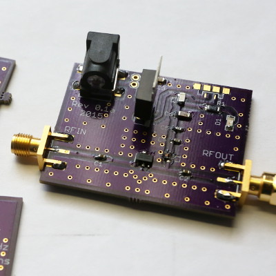
I created a very simple circuit/PCB for a board with an ADL5536 on it to amplify some weather satellite signals (around 137MHz). It's fed with a 9V battery through the DC jack. I ordered a copy of this board at OSH Park, and they turned out fine.
Remark: I had planned to have the option to either feed it through a DC jack, via simple wire connection, or through a micro-USB connector. The USB connector I ordered had through-hole feet, so they didn't fit on the PCB. Fortunately, it turns out that the DC jack is actually the best solution to feed it anyway, so you can leave that component out if you'd want to build it.
It's also my first PCB ever, so there are some flaws of course :) (like the probably-useless micro-USB connector, and the fact that it could be made smaller... but at least I found this easy to solder)
Download the Eagle files Created with Eagle Light 7.3 (I wanted to add some grounding vias, so no KiCad for me yet) and Sparkfun components to create it.
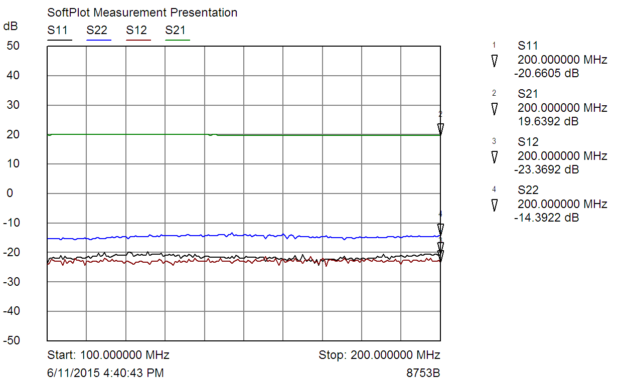
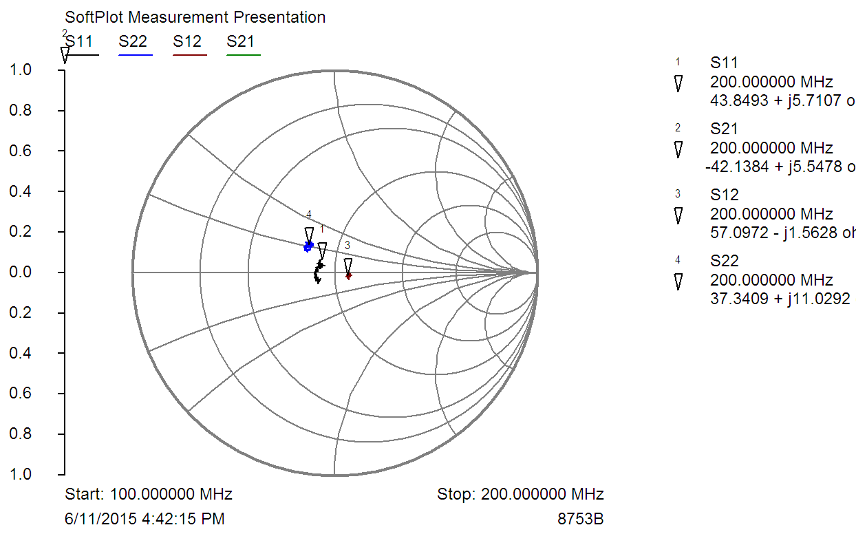
Some S-parameter measurements over the 100MHz-200MHz range:
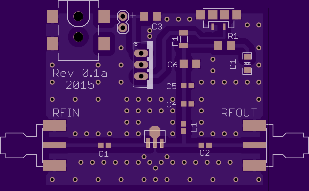
- IC1: LM7805CT voltage regulator
- U1: ADL5536ARKZ-R7 IF amplifier
- L1: 470nH 0603 (such as Coilcraft 0603LS-471XJLC)
- C1, C2: 0.1uF 0603 (such as GRM188R72A104KA35D)
- C3: 0.33 uF 1206 (such as GRM319R71H334KA01D)
- C4: 68 pF 0603 (such as GRM1885C1H680GA01D)
- C5: 1.2 nF 0603 (such as GRM1885C1H122FA01D)
- C6: 1uF 1206 (such as GCJ31MR71H105KA12L)
- RFIN, RFOUT: side-mount SMA connectors
- JP2: DC power jack (such as PJ-002AH-SMT-TR)
- F1: 0.5A fuse 1206
- D1: Red LED 1206
- R1: 330 Ohm 1206